|
Dalian Metery Technology Co.,Ltd
|
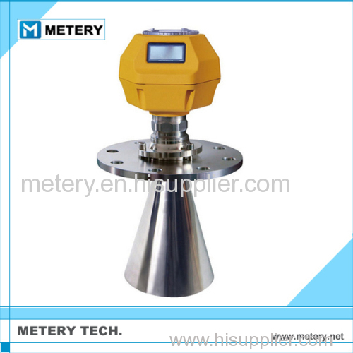
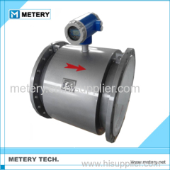
High Frequency Digital Guided Wave Rod Radar Gauge
| Price: | 200.0~1500.0 USD |
| Payment Terms: | T/T,L/C |
| Place of Origin: | Liaoning, China (Mainland) |
|
|
|
| Add to My Favorites | |
| HiSupplier Escrow |
Product Detail
High Frequency Digital Guided Wave Rod Radar Gauge
1.Scale:0~20/35 Meter
2.Output signal:4~20mA, Hart
3.Accuracy:1mm
Measuring principles
Guided wave radar is a gauge based on time stroke principle, the radar wave is running at speed of light, the running time can be converted to material level signal through electric components. The sensor emit high frequency impulse and transmit along the cable, when impulse meets the material surface, it reflects back and is received by receiver inside the gauge, and converts the distance signal to material level signal.
Input
The reflected impulse signal is transmitted along the cable to the circuit of the gauge; the microwave processor processes this signal, and recognizes the wave echo of the microwave impulse from the material surface. The correct wave echo signal is recognized by the intelligent software, the distance from the material surface D is proportional to the time stroke of the impulse T:
D=C×T/2
Among them, C is the velocity of light.
As the distance of the empty tank E is known, so L is:
L=E-D
Output
By inputting empty tank height E (=cero point), full tank height F (=full measuring range) and some application parameters are set, the application parameters will automatically make the gauge adapted to the measuring environment, it corresponds 4-20mA output.
Products:
XKTRD70 series of guided wave radar material level gauge | |||
types | MT801 | MT802 | MT803 |
Application | Liquid, solid granules | Liquid, solid granules | Liquid |
Measuring range | 30 meters | 6 meters | 6 meters |
Process connection | Screw, flange | Screw, flange | Screw, flange |
Process temperature | -40-250°C | -40-250°C | -40-250°C |
Process pressure | -1.0-40bar | -1.0-40bar | -1.0-40bar |
Precision | ±1mm | ±1mm | ±1mm |
Frequency range | 100MHZ-1.8GHZ | 100MHZ-1.8GHZ | 100MHZ-1.8GHZ |
Anti-explosion/safety grade | EXiaIICT6/IP68 | EXiaIICT6/IP68 | EXiaIICT6/IP68 |
Signal output | 4…20mA/HART(two phases) | 4…20mA/HART(two phases) | 4…20mA/HART(two phases) |
Measuring range Description: H----measuring range L----distance of empty tank B----blind area at the top E----minimum distance between sensor and tank wall. The blind area at the top refers to the minimum distance between material max. level and the measuring reference point. The blind area at the bottom refers to the distance near the very bottom area of the cable that can not be measured precisely. The distance between the blind area at the top and the blind area at the bottom is the effective measuring distance. Attention: Only when the material is between the blind area at the top and the blind area at the bottom, a reliable measurement of the material level inside the tank can be secured. |
Related Search
High Frequency Machine
High Frequency Transformer
High Frequency Welding Machine
High Frequency Power Supply
High Frequency Heating Machine
High Frequency Welding
More>>
Find more related products in following catalogs on Hisupplier.com
Related Products


Company Info
Dalian Metery Technology Co.,Ltd [China (Mainland)]
Business Type:Trading Company
City: Dalian
Province/State: Liaoning
Country/Region: China (Mainland)
|
Michael Sun:
|
|
Michael Sun:
|
You May Like:


Product (14)
- Ultrasonic flowmeter (1)
- Others (13)
